Technical questions
Most lights are designed for an operating voltage of 8V (2S LiPo/LiIon) and can be used directly with this voltage. Additionally, by soldering in an extra resistor (see article RESCARD), the light can also be operated with 3S/12V. However, this is only a temporary solution for compatibility and is only practical for small systems. It does not provide additional brightness, only produces more heat.
Some lights, especially strobes for gliders, can only be operated at 12V/3S. Please refer to the technical details of the specific light.
There are position/navigation lights that are typically switched on for the duration of a model flight, with an operating time of approximately 7-8 minutes.
There are Spotlights used as landing lights during approach, which should be operated for about 2-3 minutes.
There are flashing and strobe lights used as beacons or strobes, which should only flash intermittently to avoid overheating. Observe the duty cycle and check the operating temperature in your setup.
The duty cycle is the ratio of on-time to off-time. For example, 1 second on and 10 seconds off corresponds to 10%. Strobe lights can generally operate with a duty cycle of 5-15% without overheating, while beacons can go up to 25%. If a light becomes too warm, use a shorter flash pattern, increase the pauses, or improve cooling. A triple flash generates three times as much heat as a single flash!
The resistor for 3S operation must be installed somewhere in the light's circuit, and the exact position does not matter. It is added in addition to any pre-installed resistor. Every LED requires current regulation, as operating without it will instantly destroy the LED.
Since each light is designed for 2S operation, two lights can be connected in series to a 4S setup, or three lights to a 6S setup. However, ensure that the controller's maximum voltage is not exceeded.
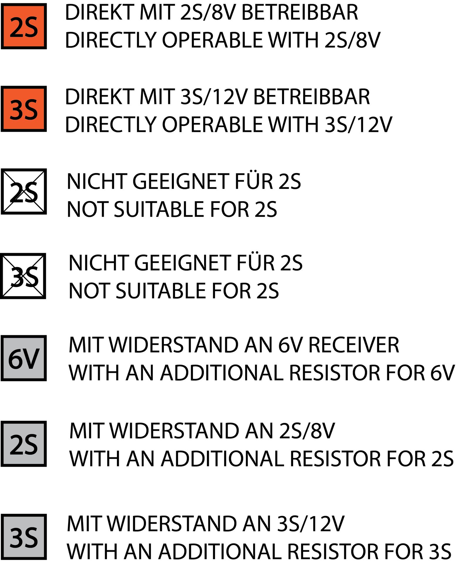
Operating at a higher voltage does not provide any advantages in terms of brightness or visibility. The excess voltage is simply dissipated through the resistor to make the system compatible with the power source. While this is a simple solution for small systems, for larger systems, we recommend using a BEC system if 3S is required as the supply voltage.
These resistors can be used for operation with 3S: RESCARD
Cables can be extended within normal limits without issues. Common sizes are 0.35mm², while 0.5mm² is advantageous for high-power lights. The losses of 2-3m of cable are insignificant.
Existing resistors can be relocated but must remain within the light's circuit.
Each light can, in principle, be connected directly to a 2S battery, where it would remain continuously lit. However, lights are usually connected to a controller to create flash/blink patterns and allow them to be turned off via remote control.
Yes, the uniLIGHT system is designed so that virtually any number of lights can be operated in parallel, including lights of different colors and power levels. The limiting factors are the power supply and controller's load capacity. Typical lighting systems do not usually reach these limits; only very large, complex systems could cause overloads. In such cases, strobes and beacons can be repositioned in order to reduce peak current.
Use weight-optimized cable sets designed for the power of your lighting and the size of your model. For small lights, cables with 0.14mm² are sufficient, while normal lights require 0.25mm², and high-power lights can use 0.5mm². Thicker cables are always better but are less efficient due to their increased weight.
Our products are suitable for typical model environments and can withstand temperatures from -20°C to +70°C. The lights themselves can reach operating temperatures of 60-70°C, while resistors in cables may become significantly hotter, which is not a concern. We use only silicone or PTFE cables, but extensions can be made from any cable material.
Many of our products are not waterproof on its own because they are supposed to be installed first. If the lights are securely glued, they will become waterproof.
The light caps are made of injection-molded polycarbonate, which is extremely shatter-resistant. However, if they scrape against the ground, they may become optically dull and will significantly reduce the light energy output.
The electrical power output of lights is not very indicative; it is merely a reference value. The emitted light output (lumens) is much more important. This data is available in the technical specifications.
To calculate the required battery capacity, sum up the nominal currents of all lights. Beacons are calculated at approximately 1/3 of their nominal current, and strobes at about 1/5. Landing light usage is critical and is calculated at around 1/2 of its nominal current. This gives the total energy requirement per hour. For instance, if you calculate a total current of 3000mA, you will need approximately 1500mAh for three flights.
Installation and Connection
The lights are essentially ready for use for the flight as delivered. The operating time of 6-8 minutes depends on the heatsink's thermal capacity. Special care with Styrofoam is not necessary, as navigation lights tolerate temperatures of 60-70°C. However, strobes and beacons can become significantly hotter if used incorrectly, so always follow proper usage guidelines and check temperatures during initial operation.
The transparent light caps can be glued on using any glue typically used for attaching canopy covers. Commonly recommended options include high-quality transparent epoxy, canopy glue, silicone, or various multi-purpose adhesives. CA glue (super glue) is NOT suitable because it dries opaque.
Heatsinks can be attached with a small amount of CA glue if there is a larger, flat surface, as the thin layer ensures good thermal transfer. For thicker joints or flat-to-round connections (e.g., landing gear), a thermally conductive adhesive is recommended.
The lights are usually mounted in the model using epoxy (for permanent attachment) or silicone, which is slightly easier to remove if necessary.
From our experience, the best method is to first securely and tightly glue the cap to the lighting unit.
Afterward, adjust the light on the model and create the necessary openings. Be cautious during this stage, as the lights are mechanically sensitive until firmly mounted—pressing on the cap while the heatsink is against an obstacle can quickly damage the circuit board.
Next, feed the cables through and secure the light to its mounting position using epoxy, canopy glue, or silicone. Excess adhesive should be cleaned off immediately. Ensure the heatsinks are not left loose or free-swinging inside the model (especially with combustion engines), as this can lead to damage over time.
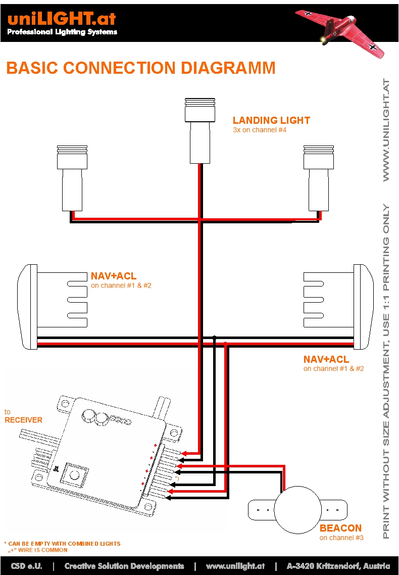
Each standard light requires two cables (e.g., landing lights, beacons/strobes, navigation lights). DUAL lights, however, require three cables: the twisted pair typically represents the strobe’s negative pole and the shared positive pole, while the single cable is the navigation light’s negative pole.
In our lighting systems, the positive pole can be shared, while the negative pole is switched. The positive poles are interconnected within the controller, so not all connector slots need to be occupied.
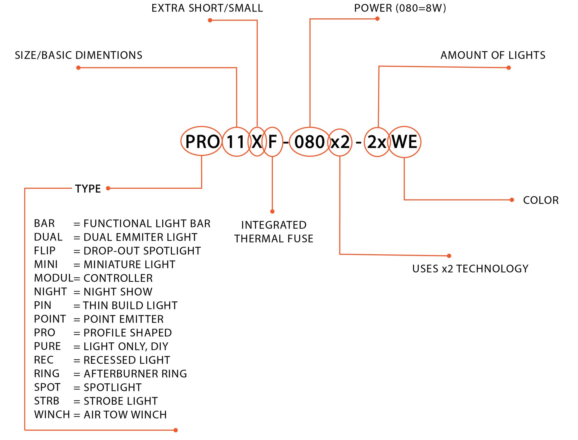
Lights with the "F" index in their product code feature an integrated thermal fuse that protects the light against gradual overload. At approximately 65°C, the light either shuts off or begins flashing to prevent further heating. Once the lamp cooled off, it will resume normal operation.
Note that the light must cool off completely to provide its standard operating duration. For example, if it is still at 45°C when restarted, the operating time will be reduced significantly leading to it shuting off again.
Yes, the lights are designed for use in model aircraft with an approximate operating time of 6-8 minutes. After each flight, a cooldown period is required to allow the heat to dissipate gradually.
If you need continuous operation, e.g., for an exhibition, the operating voltage must be reduced. Our BEC systems can be used in DEMO mode for this purpose.
The weight of the lights correlates linearly with their power—higher power requires more aluminum mass. We generally offer 2-3 power variants for most product lines, allowing you to choose the best fit. Keep in mind that sufficient power for visibility in daylight is key.
Generally -yes, but operating times and temperature must be considered. If extended operation is desired, the aluminum mass may need to be increased. Note that distances in ground-based vehicles are significantly smaller than in aircraft, so high-power lights can quickly become too bright. For cars and boats, the weakest light types are typically sufficient.
uniCONNECT
We primarily offer the CABLE and DIRECT connector series. The additional types, LITE and HEADER, belong to the DIRECT connector subgroup and share the same general parameters.
CABLE connectors feature one side (the socket) permanently installed, while the other side (the plug) is free, attached to a cable, and inserted using a locking mechanism.
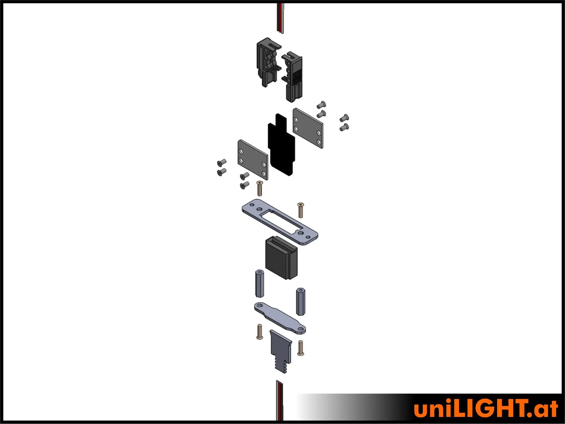
DIRECT connectors have both sides permanently installed, with the connection established directly when assembling the wings. The sockets are somewhat movable and flexibly mounted to accommodate minor movements but cannot carry the load and must be installed precisely.
LITE connectors are a simplified version of the DIRECT connectors. Here, the socket is embedded in a silicone bed to retain some flexibility. This series is more compact since it lacks mechanically defined decoupling.
HEADER connectors resemble DIRECT connectors but allow UNI 3-pin plugs to be connected directly instead of soldering. However, this results in a "plug-to-plug-to-plug" configuration, which is suboptimal for a reliable connection.
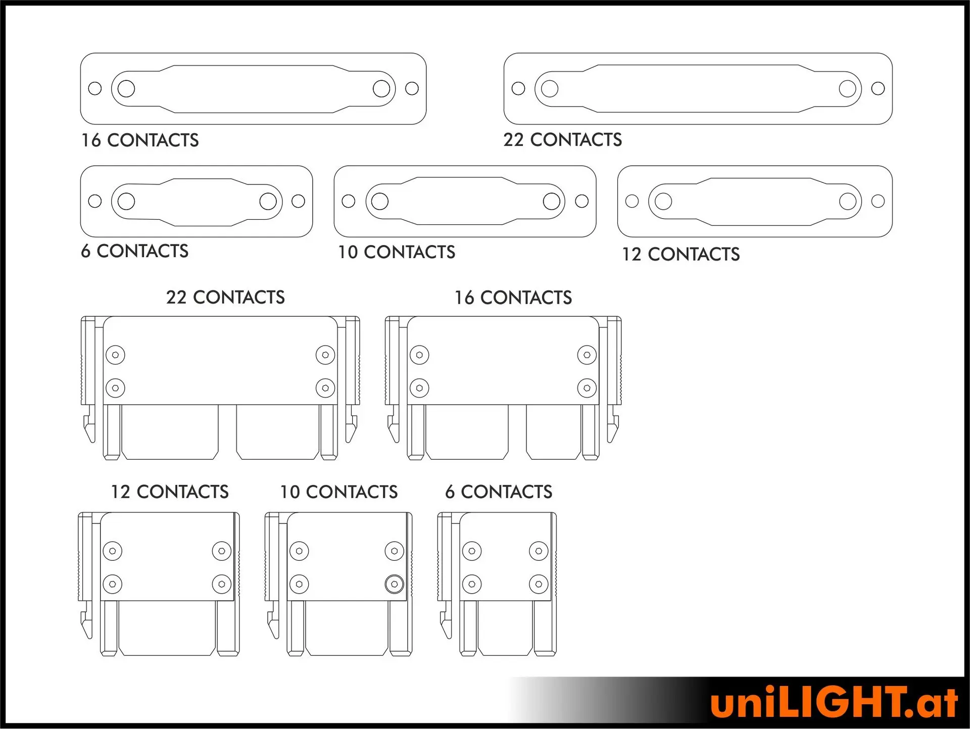
The connectors support the use of individual contacts or contact pairs. Contact pairs utilize both the upper and lower sides of the contact blades to transmit signals and power. For a reliable connection, major control channels should always be routed through primary contacts, while additional functions, such as lighting, can use secondary contacts. This ensures that main functions always have dual transmission paths in case of contamination, damage, or poor installation.

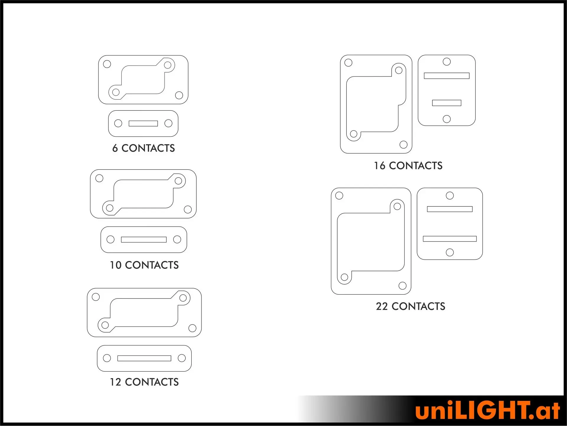
Servos always require 3P contacts, while 4S contacts are typically sufficient for light (shared positive pole). A 6P4S connector can handle two servos and lighting. A 12P4S connector can handle four servos and lighting. A 9P10S connector can handle three servos and numerous secondary functions. An 8P6S connector, one of the most common setups, can handle two servos and the landing gear on primary contacts, and lighting with brakes on secondary contacts.
We offer affordable DIY kits, which require full assembly by the customer. Good soldering skills are necessary, as tight spaces require precise soldering of fillets. Each package includes two pairs of connectors.
The most common version is Ready-to-Wire (RTW), which comes pre-assembled except for the cables, which must be soldered. These kits also include two pairs per package.
Many connectors are available in the Ready-to-Run (RTR) version, which is fully assembled, including wiring with cables directly connected 1:1. The cable can be trimmed on one side, and the remaining 3-meter cable length can be routed freely from the other connector end. Due to the extensive cabling involved, these connectors are sold as single pairs.
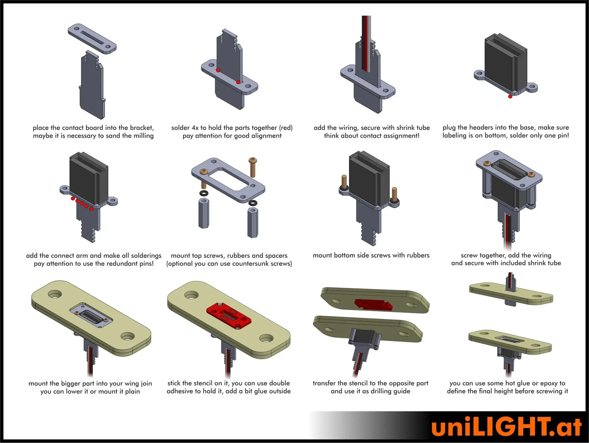
The DIRECT connector is assembled step-by-step as shown in the instructions (DIY kit). For RTW connectors, pre-assembly is already completed.
Since DIRECT connectors rely on a fixed connection, precise and aligned installation is essential for proper operation. If this is beyond your skill level or you are uncertain, consider seeking assistance or using a CABLE connector instead.
While the DIRECT connector is flexibly mounted, this mounting accommodates operational movements only and cannot absorb mechanical forces from the connection. Misalignment can create excessive burden—for instance, moving a 1-meter-long wing can exert up to 100 times the force on the connector if manipulated on the other end. These forces exceed what any connector can handle.
Installation requirements for a DIRECT connector:
- Flat mounting surfaces without movement (floating connections are unsuitable).
- The wing root should ideally be at a 90° angle to the connection direction.
- Space for the connector of approximately 5 mm between the wing root and mounting surface (may need adjustment).
When these conditions are met, use the included template or a reference video ( Einbauvideo ) for installation.
We additionally recommend an extra steps during the installation of the blade/connector, as it is unfortunately common for proper parallel alignment or precise installation to be neglected, leading to mechanical damage. Even slightly misaligned screws can cause displacement. By following the additional steps below, a reliable mounting can always be achieved:
- Install the socket
- Transfer the plug's position according to the template
- Ensure sufficient space for the cable
- Verify the connection before fixing the plug in place
- Partially slide in the wing/tailplane, with the contact blades inserted into the socket.
- Apply a bead of thickened resin (thixotropic) to the back-side of the contact blades and now fully slide the wing/tailplane in its place.
- Allow the adhesive to cure in a stress-free state.
- Aditionally, you could then secure the area with more adhesive or screws for a stable connection.
The CABLE connector assembly follows the step-by-step instructions provided (DIY kit). For RTW versions, the socket is pre-assembled, while the plug requires soldering and assembly.
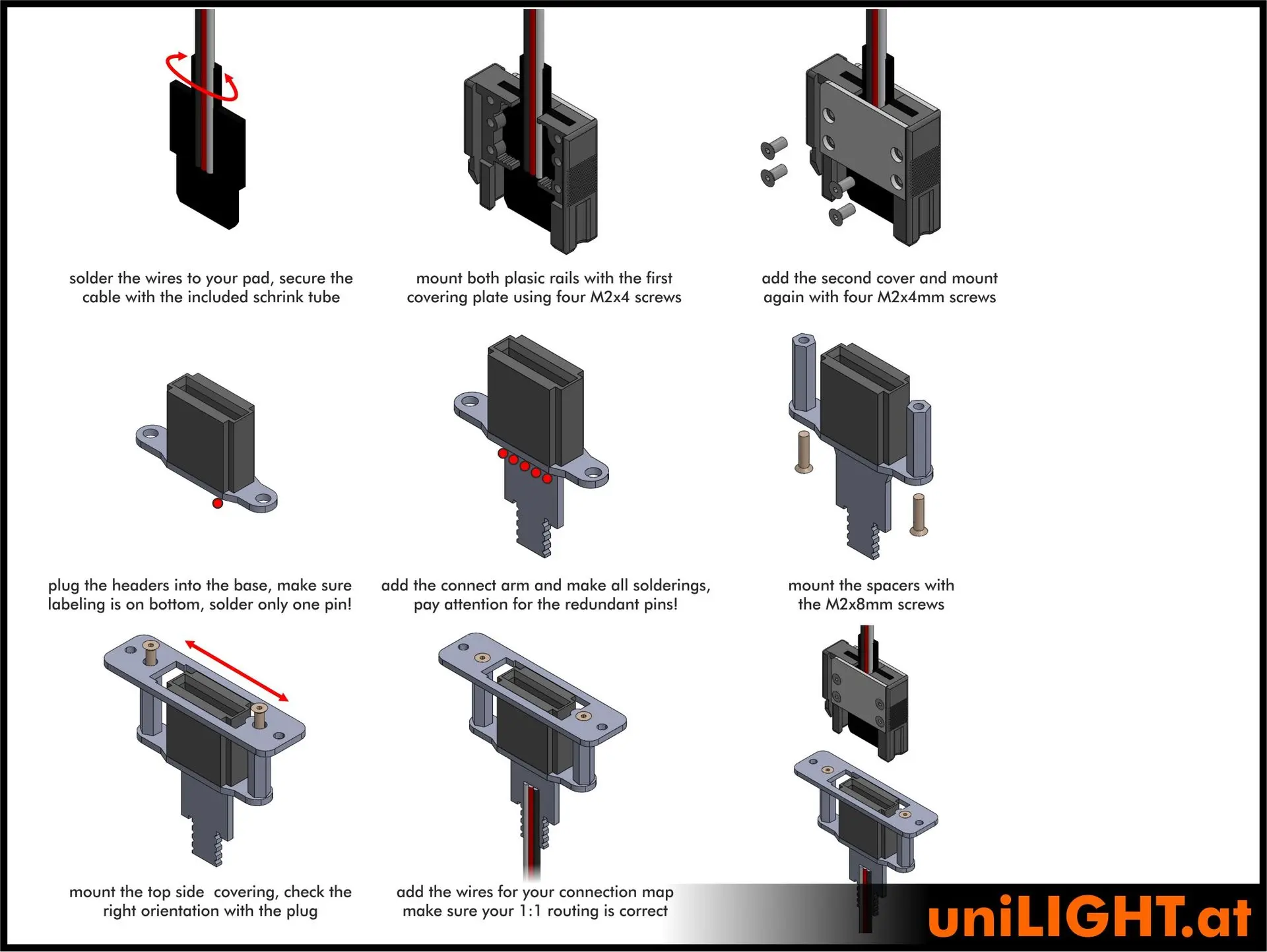
Installation is generally straightforward. The socket is typically mounted in the fuselage at the root. Just ensure there is enough space for the locking tabs.
The cables are soldered to the plug and secured with the included heat-shrink tubing. Make sure to press the shrink tubing flat so the side plates can be installed. You can insert the plug into the socket with the tabs in place and screw the side plates onto the tabs.
If locking strength is insufficient, gently heat the tabs' upper surface to increase tension. Additional locking tabs are available in various colors.
There are two main causes for a solder pad detaching. Either the pad was soldered for too long at excessive heat, or the cable was mounted without using heat-shrink tubing, resulting in mechanical tearing. In such cases, the cable can also be soldered to the adjacent groove, though this requires some soldering experience.
The second common issue is the detachment of solder pads that hold the blade connectors to the plug housing. This occurs only if the plug has been mechanically bent—a solder joint itself cannot bend. If the blade connectors on double-row plugs are not perfectly parallel, the solder joint must first be opened before it could be realigned.
If these pads break during operation, it indicates a mechanical alignment problem. The plug will not disconnect during use, but loose blade connectors may become evident when disassembling the wings. The solder joints primarily serve as a minor safeguard. Should this issue arise, the blade connectors can also be secured with a small amount of thickened epoxy.
Solder joints within the plugs are typically left uncovered, allowing for easy inspection. No exposed metallic parts should be loose within a flight model though. However, the solder joints can be isolated with hot glue or a rubber coating.
The most common cause of problems is poor, weak, or misaligned installation. Even experienced builders may occasionally overlook parallel alignment during assembly. A slightly twisted plug is the most dangerous misalignment, as it generates the highest mechanical forces. Installing the plug in a bed of adhesive yields the best results.
Oxidized contacts may occur despite gold plating, depending on the presence of dirt, moisture, or chemicals. Always ensure contacts are clean. With all uniCONNECT plugs, the contacts remain clearly visible and can be inspected at any time. Periodically applying contact grease can help prevent oxidation and contamination.
Excessive tilting of the blade connectors, excessive force, or dirt can damage or bend the springs inside the sockets. To correct this, the black plastic base can be lifted, and the springs inspected and, if necessary, adjusted to restore proper tension.
KingMax Servo
KingMax Hobby Co., Limited was established in 2004 in Hong Kong and specializes in the development and manufacturing of high-quality servos for RC models, UAVs, and robotics. Like most servo manufacturers, KingMax operates in China and supplies various industries and brands. KingMax servos are recognized worldwide under different brand names.
KingMax offers a wide range of servo types suitable for diverse applications. After years of utilizing KingMax servos in its own products, uniLIGHT has taken over the distribution of the KingMax brand for Germany and Austria. From KingMax's extensive product range, uniLIGHT has selected models with the following features:
- Variety Wing Servos: Available in various sizes for gliders and all models with thin wings.
- Digital Servos Only: For more precise control and higher performance.
- High-Voltage (HV) Servos: Designed for use with 2S LiPo batteries and demanding applications.
- Mini- and Micro-Servos: Ideal for smaller models and limited space.
- Metal Gear Servos: For maximum durability and resilience.
- Standard Servos: Available in various classes, including coreless, brushless, and partial/full aluminum housing.
- Affordable to Premium Servos: Covering all applications from versatile all-rounders to high-end top-tier servos.
uniLIGHT.at decided to include KingMax servos in its product line due to their high quality, reliability, and excellent price-performance ratio. These servos have already been extensively tested and proven among uniLIGHT's own product line and in personal use.
Towing-Winch
Rope guide The winch rope must be guided from the fuselage feedthrough to the bobbin to enable knot-free winding. Depending on the winding speed, sufficient aerodynamic braking force should be present.
uniLIGHT PLUS Data interface for extended winch configuration. Datenschnittstelle zur erweiterten Konfiguration der Winde
EXTERNAL Signal Connection point for a uniLIGHT Strobe Light to visually display the EXTERNAL signal. This signal indicates the operational status of the winch.
Internal signal BLUE Displays the receiver signal and internal status.
Winding motor Brushless electric motor with belt drive to the spool. Ensure the motor rotates freely and check its rotation direction as specified in "Mounting position".
Release servo Integrated high-performance servo for emergency winch rope release (full metal, 95 Ncm).
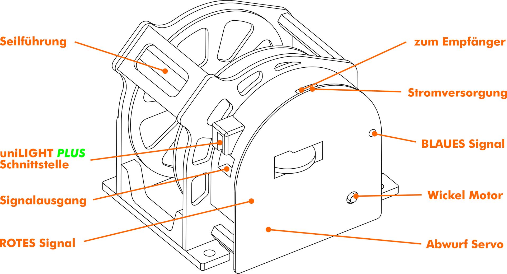

NEUTRAL (1500µs) The operating modes are activated through servo. In neutral mode, the winch remains idle. The winch rope is locked, and the winch itself enters standby mode. This mode is typically used during towing. The rope can be pulled out of the model, attached to the glider, and the towing operation can begin.
EMERGENCY RELEASE (~1800µs) In this mode, the winch rope is usually unspooled, the motor is inactive, and the locking pin is opened, releasing the rope to prevent damage to the towplane in critical situations.
DYNAMIC TOW (~1400µs) This mode helps maintaining winch rope tension during towing (e.g. to assist less experienced in towing pilots).
RETRACT (~1200µs) After releasing the glider, this mode retracts the winch rope for return flight and landing. With the winch rope retracted, aerobatics and low-approach landings can be performed without restrictions.
In the neutral standby mode, the winch operates in idle mode. The winch rope is locked, and if the release servo and motor are deactivated via the uniLIGHT.DESK configuration, all components are shut down. This allows normal towing operation without energy consumption, while all functions remain available at any time. This state is indicated by a simple, short blinking light.
In the "emergency release" mode, the central locking pin in the middle of the bobbin is opened, allowing the winch rope to be released in critical situations. Normally, the winch rope is already fully extended, with the load resting solely on this pin. Ensure structural integrity in which the loop of the winch rope cannot become entangled within your model. It is recommended to use wich ropes with sewn loops or spliced loops without knots. A rapidly blinking light pattern, both internally and externally, indicates the activation of the emergency release mode.

This mode offers the option to activate an intelligent tensioning building function via the motor if needed. Inexperienced in towing pilots often encounter slack in the winch rope, which can lead to potentially dangerous situations. In dynamic mode, the winch attempts to keep the rope taut by quickly reeling it in, but only up to the adjusted winch rope length to avoid pulling in the towed model entirely. The default setting is approximately 50% of the towline length. The motor adjusts smoothly within this range, which is variable and configurable. The winch rope is continuously reeled in when more than 50% of it is extended, with the speed increasing as the deviation grows. Note that the motor may run extensively in this mode, placing significant strain on the slipping clutch, leading to increased maintenance needs for the belt.

When towing normally in standby mode, the winch rope can be retracted back into the fuselage after the glider was released by switching to the "retract" mode.
This mode can also be used to manually maintain tension on the winch rope with by experienced in towing pilots. Unlike dynamic towing, the winch rope is reeled in across its entire length as long as there are changes in tension and position. If the winch rope remains fully extended for several seconds or there is no movement for some reason, the motor will shut off.
Ensure high-integrity mounting points, as significant forces occur during towing. Avoid placing critical components within the potential "snap-back" zone that might occur in case of releasing the winch rope under high tension.
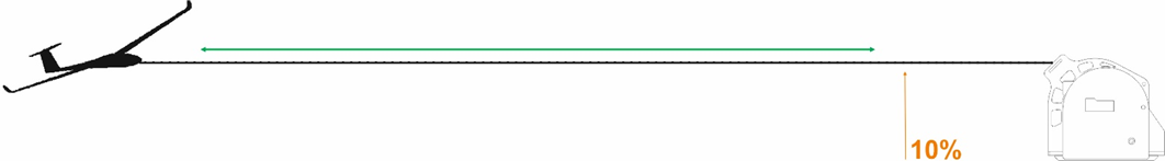
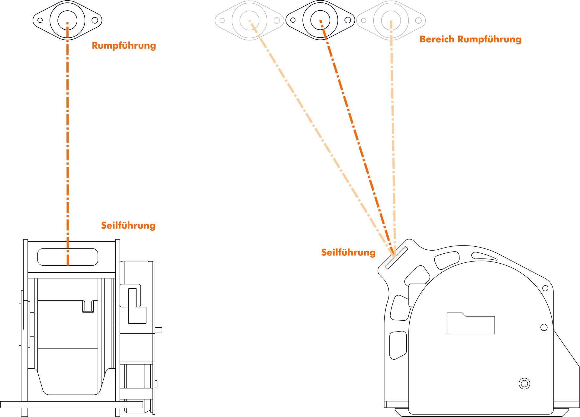
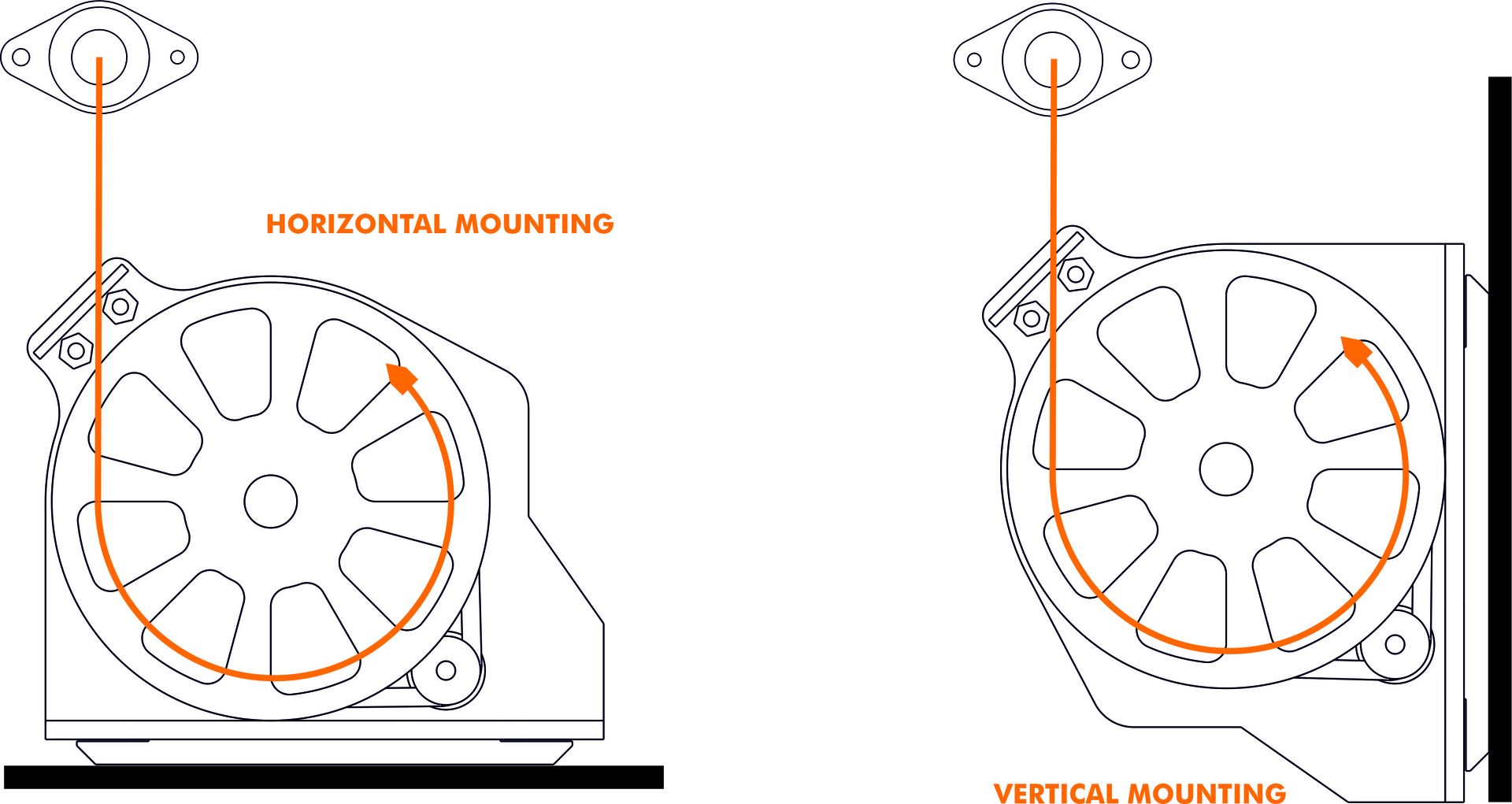
Figure 1: Ensure that the guide is mounted EXACTLY above the winch along the vertical axis of the model. If the pulling forces are not directed straight into the mounting points, damage can easily occur. Mount the winch horizontally on the fuselage floor. Deviations from these two points will result in an asymmetrical winding pattern on the bobbin.
Figure 2: On the vertical level of the winch rope guide, the fuselage entry point can be placed flexibly. Just ensure that the winch rope always runs over the metal axles and does not constantly rub against a fiberboard. The straighter the entry point is, the more reliably the winding process will function.
The towing winch can be installed horizontally on the fuselage floor or vertically on a supporting structure. Functionally, both positions are equivalent, but the winding direction must be chosen according to the orientation. If the default orientation is incorrect, adjustments can be made via the uniLIGHT PLUS interface or by swapping two motor wires.
- Optimized for minimal size and weight, ideal for electric operation and gliders up to ~10–12 kg, using winch ropes with a thickness of 0.8–1 mm.
MEDIUM
- Standard version for ambitious towing tasks, universally applicable for models up to 25 kg, using winch rope with a thickness of 1–1.5 mm.
LARGE
- Enlarged bobbin capacity for thicker and longer winch rope, suitable for models over 25 kg, using winch rope with a thickness of 1.5–2.5 mm.
Bundles
The bundles from uniLIGHT.at are specially put-together lighting packages for various aircraft types. These sets simplify the selection and installation of appropriate lighting components for your models. Those are lighting recommendations designed for scaled models matching their real-life counterparts.
Bundles are not fixed configurations—even real aircrafts of the same type may have different lighting schemes and variations depending on the country, year of manufacture, or purpose. You can use the bundle as is, which serves as a recommended configuration based on our experience for a reliable system. Alternatively, you can use the bundle as a reference and select lighting components tailored to your preferences or your model dimensions.
We offer hundreds of bundles for various aircraft prototypes, which you can find via the search function or within categorized subgroups. These categories include:
- Scale Jets
- Sport Jets
- Propeller & Turboprop aircrafts
- Helicopter
For each model and scale, we typically provide 3-4 different configurations/versions, each with a unique philosophy behind the component selection:
ENTRY: Includes a 2-channel controller, landing light(s), and a strobe light (usually white).
ECO: A budget-friendly beginner version with E4 controller and mostly economy lights, tailored to the model.
STANDARD: Features a 4-channel controller, landing light(s), a red beacon light, position lights (red and green), and, if appropriate, an ACL (white). This package offers realistic lighting at a base price with mid-range lights.
CIVIL/SPORT: Designed for show and entertainment, this package typically includes a 4-channel controller, powerful landing light(s), a red beacon light, position lights (red and green)combined with an ACL (white). It prioritizes performance and easy installation over semi-scale accuracy.
PRO: Almost always includes an 8-channel controller and all lights potentially found on the aircraft. These lights are top-tier, high-performance components to achieve the best results.
Bundles are custom-tailored complete packages for specific models or requirements, containing all necessary components. However, bundles are simply lists of individual products delivered in their original packaging. They generally do not provide a price advantage over purchasing each item separately.
Sets are more flexible and less specific, often containing basic components or accessories suitable for various applications. They are efficiently pre-produced and pre-packaged, with no customization options. However, they are significantly more affordable—typically 10-20% cheaper than if you would buy each component individually.
A bundle is merely a list of components displayed in the webshop. Adjustments are made based on customer feedback and new product availability but require updates to reflect changes.
If you don't need or want specific parts to be in your bundle, you can add the desired items according to the list to your cart individually.
Individual components from bundles can be found by using the top, general search bar. Enter the exact name or product code of the component you are looking for. The search will display the standalone product as well as the bundles that include it.
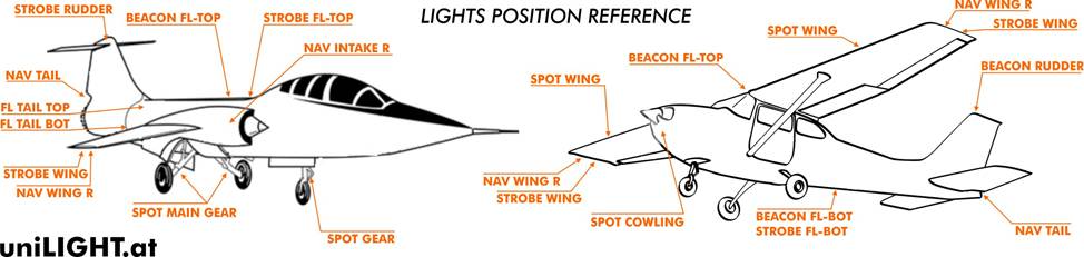
The exact positioning of the lights on your model is up to you as the model builder. Depending on your model, personal experience, and individual preferences, you decide where and how to install the lighting. Our lighting systems come with a description of their function and intended application. Beyond that, we can only provide general guidelines and recommendations based on our expertise.
We cannot provide individual sketches for each model. Instead, we offer a general reference sketch that serves as a guideline and aligns with the designations used in our products.
General questions
With the uniLIGHT system, we aim to provide powerful lighting solutions for models, ensuring they remain visible even in daylight.
Safety
uniLIGHT system makes your model more visible! Improved orientation and reduced steering errors under all weather conditions and lighting situations. We use only extremely bright lights that are clearly visible even during the day. Whether flying at great distances or in a foggy weather, good lighting keeps you on the safe side.
Aestetics
Enhance the appearance and value of your model with additional lighting features. A real eye-catcher for any model, achieving a dramatic effect with minimal effort. uniLIGHT modules enable various light effects and individual customization for your model.
Scale-accuracy
You can install realistic or simply functional, high-performance lighting—uniLIGHT makes it all possible. Our lights support high-power systems for larger scales, but even smaller models can achieve outstanding effects with these strong lights.
Smart
uniLIGHT products are easy to use and quickly operational. The lights come pre-configured for direct operation with 2S or 3S LiPo. No need to calculate resistances, and our lights ensure sufficient cooling.
uniLIGHT offers only high-performance LED systems specializing in model aviation and commercial drones. The goal is maximum performance with compact dimensions, minimal weight, and easy operation. We prioritize performance, therefore we use transparent covers with colored LEDs for the best results.
We provide intuitive and user-friendly controllers for your lighting setup. The innovative lighting program selection is integrated into the modern remote control, allowing the pilot to adjust functions directly from the transmitter at any time. On the module itself, only the blink rate can be continuously adjusted based on the model size and model-builder preferences.
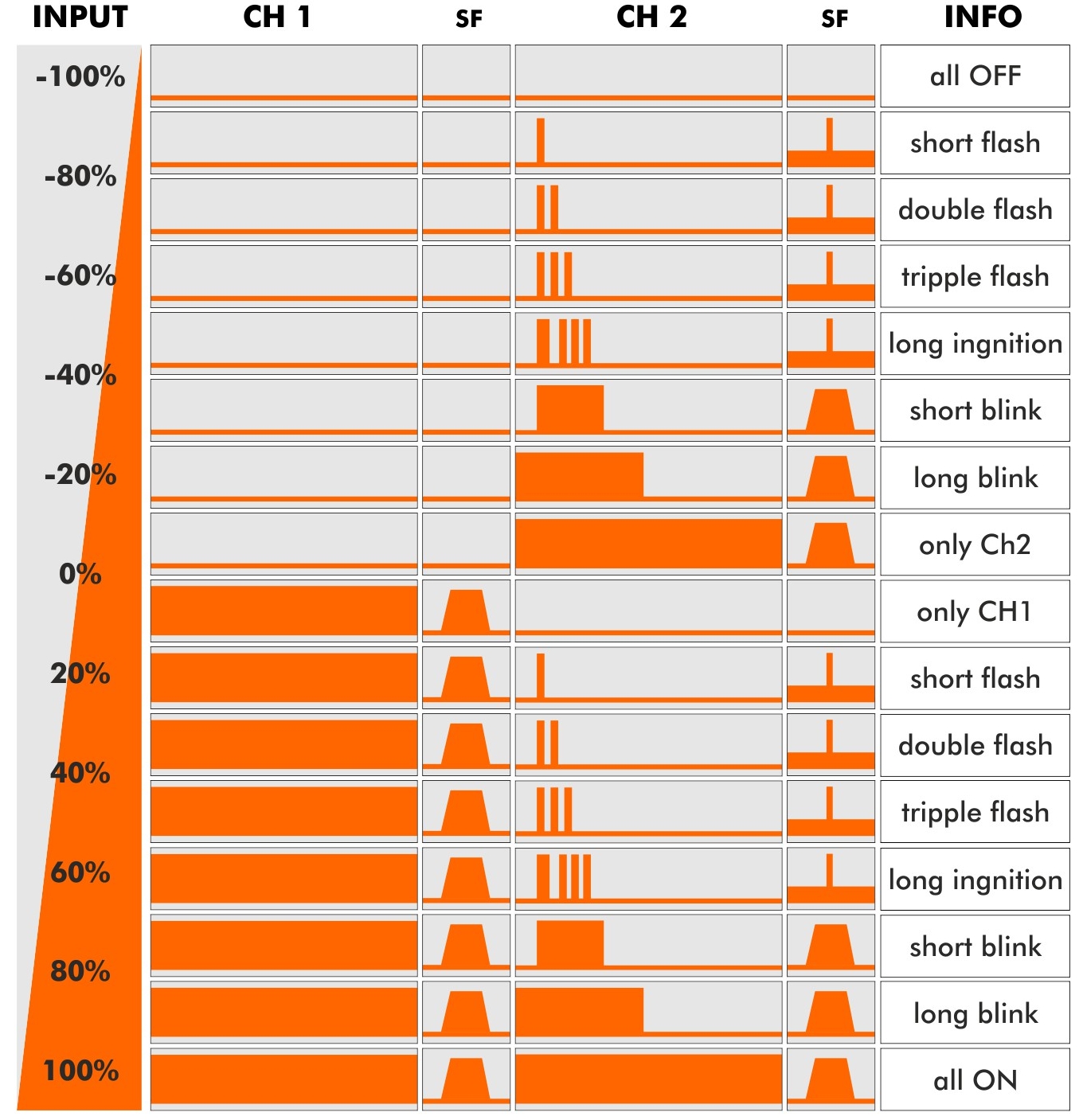
Adjust the servo signal using an analog channel to switch between effects. If you use a switch, assign it as you would for idle-up function or landing flaps. The light pattern at -30% differs from that at +20% or -60%. Refer to the description of the respective control module for the lighting chart, as it serves as the key reference for programming.
For further assistance, contact us via email or the contact form for personalized consultation. Most realistic models are already included in the bundle suggestions, which can be found using the search function or under the Bundles category and its subcategories.
Assembly instructions and mounting aids are available directly on the product pages or in the Downloads section of our website.
Shipping & Returns
Free shipping is available for orders over €130 within Austria and Germany.
Shipping costs are calculated at checkout and depend on your location and chosen courier service.
In certain countries and regions, shipping costs may subsequently increase. In such cases, we will inform you before dispatch or, in individual cases, choose an economical service provider with similar conditions.
We offer a 30-day return guarantee for all products. Items must be in their original condition, unused, and include the receipt or proof of purchase. Refunds are processed within 5–7 business days after receiving the returned item.
We ship worldwide with GLS, DPD, DHL, and UPS. If your destination is not available, please send us a message, and we will check the shipping costs.
As long as an order has not yet been dispatched, an additional order can be combined. To do so, select "Pick-up order" as the shipping method. However, we strive to process and dispatch all orders daily, so the time window is limited.
As a small company, we unfortunately cannot offer free returns or courier-collections like larger shipping giants. We aim to keep shipping costs as low as possible but must pay standard list prices. Therefore, returns often cost significantly more than the regular shipping price.
Safety and Maintenance
Always disconnect the power supply during assembly and avoid short circuits. Test the lamps for functionality before installation. Never look directly into a high-performance LED from a close distance.
Yes, replacement parts are available for most products after consultation, though self-installation comes in question as it is often not straightforward and may be challenging.
Our LEDs have a lifespan of many thousands of hours, far exceeding what a model aircraft might endure. However, operating temperature can become problematic if the lights are used beyond their intended range. Always monitor operating temperatures during use.
Batteries should be replaced every 2–3 years, depending on usage.
Support und contact
You can reach us via email or contact form. Details can be found on our contact page.
Telephone consultation is often very difficult and impractical, so we prefer informal emails.
Subscribe to our newsletter or follow us on social media.
Yes, we welcome your feedback and suggestions for improvement.
An overview of our partners can be found in the Dealers section of our website.